翻訳は機械翻訳により提供されています。提供された翻訳内容と英語版の間で齟齬、不一致または矛盾がある場合、英語版が優先します。
# SDK での回路の構築
このセクションでは、回路の定義、使用可能なゲートの表示、回路の拡張、および各デバイスがサポートするゲートの表示の例を示します。また、qubits を手動で割り当てる方法、定義されたとおりに回路を実行するようにコンパイラーに指示する方法、ノイズシミュレーターを使用してノイズの多い回路を構築する方法についても説明します。
QPU によっては、Braket でさまざまなゲートのためにパルスレベルで作業することもできます。詳細については、「[Pulse Control on Amazon Braket](braket-pulse-control.md)」を参照してください。
**Topics**
+ [ゲートと回路](#braket-gates)
+ [プログラムセット](#braket-program-set)
+ [部分測定](#braket-partial-measurement)
+ [手動 qubit 割り当て](#manual-qubit-allocation)
+ [逐語的なコンパイル](#verbatim-compilation)
+ [ノイズシミュレーション](#noise-simulation)
## ゲートと回路
量子ゲートと回路は、Amazon Braket Python SDK の [https://github.com/aws/amazon-braket-sdk-python/blob/main/src/braket/circuits/circuit.py](https://github.com/aws/amazon-braket-sdk-python/blob/main/src/braket/circuits/circuit.py) クラスで定義されています。SDK から、`Circuit()` を呼び出して、新しい回路オブジェクトをインスタンス化できます。
**例: 回路を定義する**
この例ではまず、標準の、1 量子ビットのアダマールゲートと 2 量子ビットの CNOT ゲートから成る 4 つのqubits (ラベルは `q0`、`q1`、`q2`、`q3`) のサンプル回路を定義しています。この回路を可視化するには、次の例に示されているように `print` 関数を呼び出します。
```
# Import the circuit module
from braket.circuits import Circuit
# Define circuit with 4 qubits
my_circuit = Circuit().h(range(4)).cnot(control=0, target=2).cnot(control=1, target=3)
print(my_circuit)
```
```
T : │ 0 │ 1 │
┌───┐
q0 : ─┤ H ├───●─────────
└───┘ │
┌───┐ │
q1 : ─┤ H ├───┼─────●───
└───┘ │ │
┌───┐ ┌─┴─┐ │
q2 : ─┤ H ├─┤ X ├───┼───
└───┘ └───┘ │
┌───┐ ┌─┴─┐
q3 : ─┤ H ├───────┤ X ├─
└───┘ └───┘
T : │ 0 │ 1 │
```
**例: パラメータ化された回路を定義する**
この例では、自由パラメータに依存するゲートを持つ回路を定義します。これらのパラメータの値を指定することで、新しい回路を作成することもできれば、回路を送信する際に特定のデバイスで量子タスクとして実行することもできます。
```
from braket.circuits import Circuit, FreeParameter
# Define a FreeParameter to represent the angle of a gate
alpha = FreeParameter("alpha")
# Define a circuit with three qubits
my_circuit = Circuit().h(range(3)).cnot(control=0, target=2).rx(0, alpha).rx(1, alpha)
print(my_circuit)
```
パラメータ化された回路からパラメータ化されていない新しい回路を作成するには、次のように、単一の `float` 引数 (すべての自由パラメータが取る値)か、各パラメータの値を指定するキーワード引数を回路に指定します。
```
my_fixed_circuit = my_circuit(1.2)
my_fixed_circuit = my_circuit(alpha=1.2)
print(my_fixed_circuit)
```
`my_circuit` は変更されていないため、それを固定パラメータ値で使用して多くの新しい回路をインスタンス化できます。
**例: 回路のゲートを変更する**
次の例では、control 修飾子と power 修飾子を使用するゲートを持つ回路を定義しています。これらの修飾を使用して、制御された `Ry` ゲートなどの新しいゲートを作成できます。
```
from braket.circuits import Circuit
# Create a bell circuit with a controlled x gate
my_circuit = Circuit().h(0).x(control=0, target=1)
# Add a multi-controlled Ry gate of angle .13
my_circuit.ry(angle=.13, target=2, control=(0, 1))
# Add a 1/5 root of X gate
my_circuit.x(0, power=1/5)
print(my_circuit)
```
ゲート修飾子はローカルシミュレーターでのみサポートされています。
**例: 使用可能なすべてのゲートを見る**
次の例は、Amazon Braket で使用可能なすべてのゲートを確認する方法を示しています。
```
from braket.circuits import Gate
# Print all available gates in Amazon Braket
gate_set = [attr for attr in dir(Gate) if attr[0].isupper()]
print(gate_set)
```
このコードからの出力には、すべてのゲートが一覧表示されます。
```
['CCNot', 'CNot', 'CPhaseShift', 'CPhaseShift00', 'CPhaseShift01', 'CPhaseShift10', 'CSwap', 'CV', 'CY', 'CZ', 'ECR', 'GPhase', 'GPi', 'GPi2', 'H', 'I', 'ISwap', 'MS', 'PRx', 'PSwap', 'PhaseShift', 'PulseGate', 'Rx', 'Ry', 'Rz', 'S', 'Si', 'Swap', 'T', 'Ti', 'U', 'Unitary', 'V', 'Vi', 'X', 'XX', 'XY', 'Y', 'YY', 'Z', 'ZZ']
```
これらのゲートは、そのタイプの回路のメソッドを呼び出して、回路に追加できます。例えば、`circ.h(0)` を呼び出し、最初の qubit にアダマールゲートを加えます。
**注記**
ゲートが所定の位置に追加され、以下の例では、前の例に挙げたすべてのゲートを同じ回路に追加しています。
```
circ = Circuit()
# toffoli gate with q0, q1 the control qubits and q2 the target.
circ.ccnot(0, 1, 2)
# cnot gate
circ.cnot(0, 1)
# controlled-phase gate that phases the |11> state, cphaseshift(phi) = diag((1,1,1,exp(1j*phi))), where phi=0.15 in the examples below
circ.cphaseshift(0, 1, 0.15)
# controlled-phase gate that phases the |00> state, cphaseshift00(phi) = diag([exp(1j*phi),1,1,1])
circ.cphaseshift00(0, 1, 0.15)
# controlled-phase gate that phases the |01> state, cphaseshift01(phi) = diag([1,exp(1j*phi),1,1])
circ.cphaseshift01(0, 1, 0.15)
# controlled-phase gate that phases the |10> state, cphaseshift10(phi) = diag([1,1,exp(1j*phi),1])
circ.cphaseshift10(0, 1, 0.15)
# controlled swap gate
circ.cswap(0, 1, 2)
# swap gate
circ.swap(0,1)
# phaseshift(phi)= diag([1,exp(1j*phi)])
circ.phaseshift(0,0.15)
# controlled Y gate
circ.cy(0, 1)
# controlled phase gate
circ.cz(0, 1)
# Echoed cross-resonance gate applied to q0, q1
circ = Circuit().ecr(0,1)
# X rotation with angle 0.15
circ.rx(0, 0.15)
# Y rotation with angle 0.15
circ.ry(0, 0.15)
# Z rotation with angle 0.15
circ.rz(0, 0.15)
# Hadamard gates applied to q0, q1, q2
circ.h(range(3))
# identity gates applied to q0, q1, q2
circ.i([0, 1, 2])
# iswap gate, iswap = [[1,0,0,0],[0,0,1j,0],[0,1j,0,0],[0,0,0,1]]
circ.iswap(0, 1)
# pswap gate, PSWAP(phi) = [[1,0,0,0],[0,0,exp(1j*phi),0],[0,exp(1j*phi),0,0],[0,0,0,1]]
circ.pswap(0, 1, 0.15)
# X gate applied to q1, q2
circ.x([1, 2])
# Y gate applied to q1, q2
circ.y([1, 2])
# Z gate applied to q1, q2
circ.z([1, 2])
# S gate applied to q0, q1, q2
circ.s([0, 1, 2])
# conjugate transpose of S gate applied to q0, q1
circ.si([0, 1])
# T gate applied to q0, q1
circ.t([0, 1])
# conjugate transpose of T gate applied to q0, q1
circ.ti([0, 1])
# square root of not gate applied to q0, q1, q2
circ.v([0, 1, 2])
# conjugate transpose of square root of not gate applied to q0, q1, q2
circ.vi([0, 1, 2])
# exp(-iXX theta/2)
circ.xx(0, 1, 0.15)
# exp(i(XX+YY) theta/4), where theta=0.15 in the examples below
circ.xy(0, 1, 0.15)
# exp(-iYY theta/2)
circ.yy(0, 1, 0.15)
# exp(-iZZ theta/2)
circ.zz(0, 1, 0.15)
# IonQ native gate GPi with angle 0.15 applied to q0
circ.gpi(0, 0.15)
# IonQ native gate GPi2 with angle 0.15 applied to q0
circ.gpi2(0, 0.15)
# IonQ native gate MS with angles 0.15, 0.15, 0.15 applied to q0, q1
circ.ms(0, 1, 0.15, 0.15, 0.15)
```
定義済みのゲートセットとは別に、自己定義のユニタリゲートを回路に適用することもできます。これらは、単一量子ビットゲート (次のソースコードに示すとおり) とすることも、`targets` パラメータにより定義される qubits に適用されるマルチ量子ビットゲートとすることもできます。
```
import numpy as np
# Apply a general unitary
my_unitary = np.array([[0, 1],[1, 0]])
circ.unitary(matrix=my_unitary, targets=[0])
```
**例: 既存の回路を拡張する**
命令を追加することで、既存の回路を拡張できます。`Instruction` は、量子デバイス上で実行する量子タスクを記述する量子指令です。`Instruction` 作用素には、`Gate` のみのタイプのオブジェクトが含まれます。
```
# Import the Gate and Instruction modules
from braket.circuits import Gate, Instruction
# Add instructions directly.
circ = Circuit([Instruction(Gate.H(), 4), Instruction(Gate.CNot(), [4, 5])])
# Or with add_instruction/add functions
instr = Instruction(Gate.CNot(), [0, 1])
circ.add_instruction(instr)
circ.add(instr)
# Specify where the circuit is appended
circ.add_instruction(instr, target=[3, 4])
circ.add_instruction(instr, target_mapping={0: 3, 1: 4})
# Print the instructions
print(circ.instructions)
# If there are multiple instructions, you can print them in a for loop
for instr in circ.instructions:
print(instr)
# Instructions can be copied
new_instr = instr.copy()
# Appoint the instruction to target
new_instr = instr.copy(target=[5, 6])
new_instr = instr.copy(target_mapping={0: 5, 1: 6})
```
**例: 各デバイスがサポートするゲートの表示**
シミュレーターは Braket SDK のすべてのゲートをサポートしますが、QPU デバイスは小さなサブセットをサポートします。デバイスのサポートされているゲートは、デバイスのプロパティで確認できます。IonQ デバイスの例を次に示します。
```
# Import the device module
from braket.aws import AwsDevice
device = AwsDevice("arn:aws:braket:us-east-1::device/qpu/ionq/Aria-1")
# Get device name
device_name = device.name
# Show supportedQuantumOperations (supported gates for a device)
device_operations = device.properties.dict()['action']['braket.ir.openqasm.program']['supportedOperations']
print('Quantum Gates supported by {}:\n {}'.format(device_name, device_operations))
```
```
Quantum Gates supported by Aria 1:
['x', 'y', 'z', 'h', 's', 'si', 't', 'ti', 'v', 'vi', 'rx', 'ry', 'rz', 'cnot', 'swap', 'xx', 'yy', 'zz']
```
サポートされているゲートは、量子ハードウェアで実行する前に、ネイティブゲートにコンパイルする必要があります。回路を送信すると、Amazon Braket はそのコンパイルを自動的に実行します。
**例: デバイスでサポートされているネイティブゲートの忠実度をプログラムで取得する**
忠実度情報は、Braket コンソールの **[デバイス]** ページで確認できます。同じ情報にプログラムでアクセスできると役立つ場合があります。次のコードは、QPU の 2 つの量子ビット間における 2 つの qubit ゲートの忠実度を抽出する方法を示しています。
```
# Import the device module
from braket.aws import AwsDevice
device = AwsDevice("arn:aws:braket:us-west-1::device/qpu/rigetti/Ankaa-3")
# Specify the qubits
a=10
b=11
edge_properties_entry = device.properties.standardized.twoQubitProperties['10-11'].twoQubitGateFidelity
gate_name = edge_properties_entry[0].gateName
fidelity = edge_properties_entry[0].fidelity
print(f"Fidelity of the {gate_name} gate between qubits {a} and {b}: {fidelity}")
```
## プログラムセット
プログラムセットは、1 つの量子タスクで複数の量子回路を効率的に実行します。その 1 つのタスクでは、最大 100 個の量子回路を送信することも、最大 100 個の異なるパラメータセットを持つ 1 つのパラメトリック回路を送信することもできます。このようなオペレーションにより、後続の回路実行間の時間が最短に抑えられ、量子タスク処理のオーバーヘッドが削減されます。現在、プログラムセットは Amazon Braket Local Simulatorと AQT、IQMおよび Rigettiデバイスでサポートされています。
**ProgramSet の定義**
次の最初のコード例は、パラメータ化された回路を使用する場合とパラメータのない回路を使用する場合での `ProgramSet` の構築方法を示しています。
```
from braket.aws import AwsDevice
from braket.circuits import Circuit, FreeParameter
from braket.program_sets.circuit_binding import CircuitBinding
from braket.program_sets import ProgramSet
# Initialize the quantum device
device = AwsDevice("arn:aws:braket:eu-north-1::device/qpu/iqm/Garnet")
# Define circuits
circ1 = Circuit().h(0).cnot(0, 1)
circ2 = Circuit().rx(0, 0.785).ry(1, 0.393).cnot(1, 0)
circ3 = Circuit().t(0).t(1).cz(0, 1).s(0).cz(1, 2).s(1).s(2)
parameterize_circuit = Circuit().rx(0, FreeParameter("alpha")).cnot(0, 1).ry(1, FreeParameter("beta"))
# Create circuit bindings with different parameters
circuit_binding = CircuitBinding(
circuit=parameterize_circuit,
input_sets={
'alpha': (0.10, 0.11, 0.22, 0.34, 0.45),
'beta': (1.01, 1.01, 1.03, 1.04, 1.04),
})
# Creating the program set
program_set_1 = ProgramSet([
circ1,
circ2,
circ3,
circuit_binding,
])
```
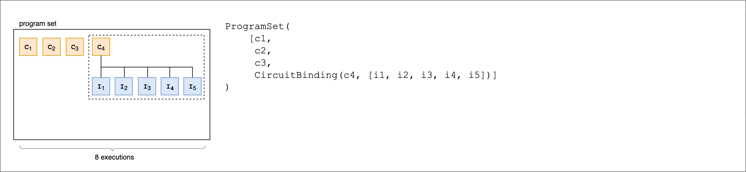
このプログラムセットには `circ1`、`circ2`、`circ3`、および `circuit_binding` の、4 つの一意のプログラムが含まれています。`circuit_binding` プログラムは 5 つの異なるパラメータバインディングで実行され、5 つの実行可能回路を作成します。パラメータを使用しない他の 3 つのプログラムは、それぞれ 1 つの実行可能回路を作成します。したがって、合計では 8 つの実行可能回路が生成されることになります。これを次の図に示します。
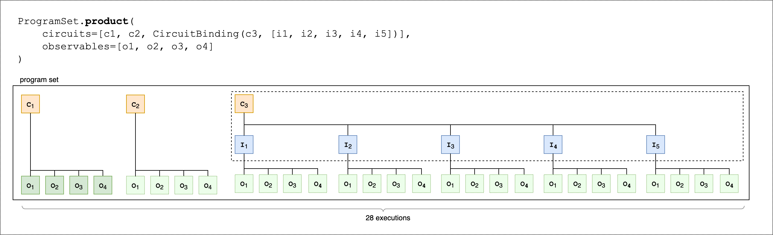
次の、2 番目のコード例は、`product()` メソッドを使用して、プログラムセットの各実行可能回路に同じオブザーバブルのセットをアタッチする方法を示しています。
```
from braket.circuits.observables import I, X, Y, Z
observables = [Z(0) @ Z(1), X(0) @ X(1), Z(0) @ X(1), X(0) @ Z(1)]
program_set_2 = ProgramSet.product(
circuits=[circ1, circ2, circuit_binding],
observables=observables
)
```
パラメータを使用しないプログラムの場合、各オブザーバブルは回路ごとに測定されます。パラメータを使用するプログラムの場合、次の図に示すように、各オブザーバブルは入力セットごとに測定されます。
次の、3 番目のコード例は、`zip()` メソッドを使用して、個々のオブザーバブルを `ProgramSet` 内の特定のパラメータセットとペアリングする方法を示しています。
```
program_set_3 = ProgramSet.zip(
circuits=circuit_binding,
observables=observables + [Y(0) @ Y(1)]
)
```
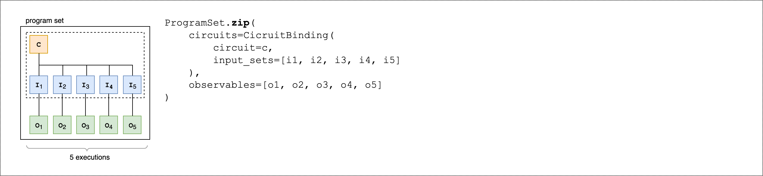
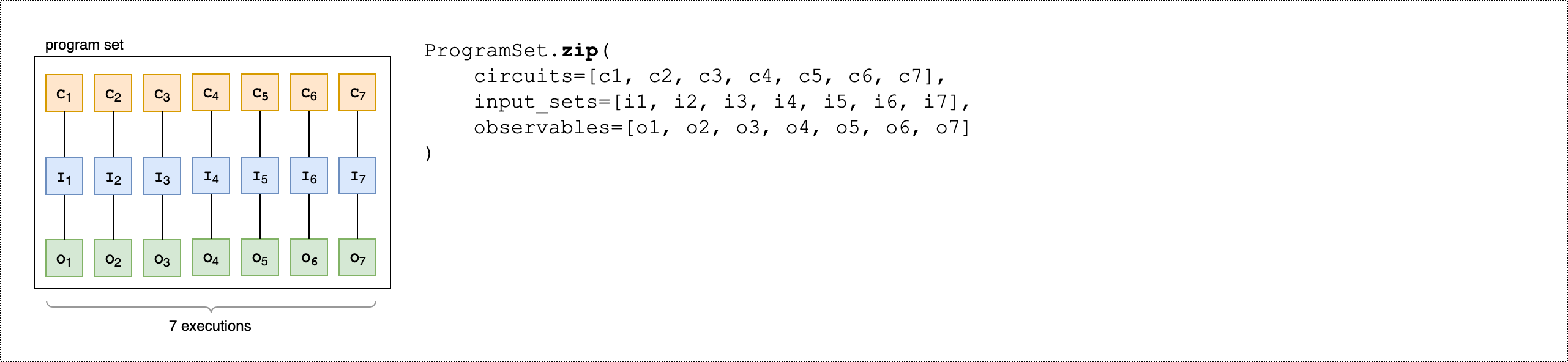
`CircuitBinding()` の代わりに、回路と入力セットのリストを使用して、オブザーバブルのリストを直接 zip できます。
```
program_set_4 = ProgramSet.zip(
circuits=[circ1, circ2, circ3],
input_sets=[{}, {}, {}],
observables=observables[:3]
)
```
プログラムセットの詳細と例については、amazon-braket-examples Github の「[プログラムセットフォルダー](https://github.com/amazon-braket/amazon-braket-examples/tree/main/examples/braket_features/program_sets)」を参照してください。
**デバイスでプログラムセットを検査して実行する**
プログラムセットの実行可能回路数は、一意のパラメータ付き回路の数と等しくなります。実行可能回路数と回路のショット数を合算するには、次のコード例を使用します。
```
# Number of shots per executable
shots = 10
num_executables = program_set_1.total_executables
# Calculate total number of shots across all executables
total_num_shots = shots*num_executables
```
**注記**
プログラムセットを使用して、プログラムセット内のすべての回路の合計ショット数に基づいて、タスクごとの料金とショットごとの料金を支払います。
プログラムセットを実行するには、次のコード例を使用します。
```
# Run the program set
task = device.run(
program_set_1, shots=total_num_shots,
)
```
Rigetti デバイスを使用する場合、タスクの一部のみが終了して残りがまだキューに入っている間、プログラムセットは `RUNNING` 状態のままになることがあります。より迅速な結果を得るには、プログラムセットを[ハイブリッドジョブ](braket-jobs-first.md)として送信することを検討してください。
**結果の分析**
`ProgramSet` 内の実行可能回路の結果を分析および測定するには、次のコードを実行します。
```
# Get the results from a program set
result = task.result()
# Get the first executbable
first_program = result[0]
first_executable = first_program[0]
# Inspect the results of the first executable
measurements_from_first_executable = first_executable.measurements
print(measurements_from_first_executable)
```
## 部分測定
部分測定を使用することで、量子回路内のすべての量子ビットを測定する代わりに量子ビットのサブセットまたは個々の量子ビットを測定できます。
**注記**
実験機能として、中間回路測定およびフィードフォワードオペレーションなどの追加機能が利用できるようになりました。「[Access to dynamic circuits on IQM devices](braket-experimental-capabilities.md#braket-access-dynamic-circuits)」を参照。
**例: 量子ビットのサブセットを測定する**
次のコード例は、ベル状態回路で量子ビット 0 のみを測定する部分測定を示しています。
```
from braket.devices import LocalSimulator
from braket.circuits import Circuit
# Use the local state vector simulator
device = LocalSimulator()
# Define an example bell circuit and measure qubit 0
circuit = Circuit().h(0).cnot(0, 1).measure(0)
# Run the circuit
task = device.run(circuit, shots=10)
# Get the results
result = task.result()
# Print the circuit and measured qubits
print(circuit)
print()
print("Measured qubits: ", result.measured_qubits)
```
## 手動 qubit 割り当て
Rigetti の量子コンピュータで量子回路を実行する場合、任意で手動 qubit 割り当てを使用して、アルゴリズムに使用される qubits を制御できます。[Amazon Braket コンソール](https://console.aws.amazon.com/braket/home)と [Amazon Braket SDK](https://github.com/aws/amazon-braket-sdk-python) は、選択した量子処理装置 (QPU) デバイスの最新のキャリブレーションデータを検査するのに役立ち、実験に最適な qubits を選択できます。
手動qubit割り当てを使用すると、回路をより正確に実行し、個々のqubitのプロパティを調べることができます。研究者および上級ユーザーは、最新のデバイスキャリブレーションデータに基づいて回路設計を最適化し、より正確な結果を得ることができます。
次の例は、明示的に qubits を割り当てる方法を示しています。
```
# Import the device module
from braket.aws import AwsDevice
device = AwsDevice("arn:aws:braket:us-west-1::device/qpu/rigetti/Ankaa-3")
circ = Circuit().h(0).cnot(0, 7) # Indices of actual qubits in the QPU
# Set up S3 bucket (where results are stored)
my_bucket = "amazon-braket-s3-demo-bucket" # The name of the bucket
my_prefix = "your-folder-name" # The name of the folder in the bucket
s3_location = (my_bucket, my_prefix)
my_task = device.run(circ, s3_location, shots=100, disable_qubit_rewiring=True)
```
詳細については、「[GitHub での Amazon Braket の例](https://github.com/aws/amazon-braket-examples)」、より具体的には、ノートブック: 「[QPU デバイスでの量子ビットの割り当て](https://github.com/aws/amazon-braket-examples/blob/main/examples/braket_features/Allocating_Qubits_on_QPU_Devices.ipynb)」を参照してください。
## 逐語的なコンパイル
ゲートベースの量子コンピュータで量子回路を実行する場合、変更を加えることなく、定義したとおりに正確に回路を実行するようにコンパイラーに指示することができます。逐語的なコンパイルを使用して、回路全体を指定どおりに正確に保持するか、または回路の特定の部分のみを保持する (Rigetti でのみ可能) ように指定できます。ハードウェアベンチマークまたはエラー緩和プロトコルのアルゴリズムを開発する場合、ハードウェアで実行するゲートと回路レイアウトを正確に指定できる必要があります。逐語的なコンパイルでは、特定の最適化ステップを無効にすることで、コンパイルプロセスを直接制御できます。これにより、回路が設計どおりに実行されるようになります。
逐語的なコンパイルは、AQT、、IonQIQM、および Rigetti デバイスでサポートされており、ネイティブゲートを使用する必要があります。逐語的なコンパイルを使用する場合は、デバイスのトポロジをチェックして、接続された qubits でゲートが呼び出され、回路がハードウェアでサポートされているネイティブゲートを使用していることを確認することをお勧めします。次に、デバイスでサポートされるネイティブゲートのリストにプログラムでアクセスする例を示します。
```
device.properties.paradigm.nativeGateSet
```
Rigetti 向けには、逐語的コンパイルと併用するために `disableQubitRewiring=True` を設定することで、qubit の再配線を無効にする必要があります。`disableQubitRewiring=False` がコンパイルで逐語的ボックスを使用するときに設定されると、量子回路は検証に失敗し、実行されません。
回路に対して逐語的なコンパイルが有効で、それをサポートしていない QPU で実行すると、サポートされていないオペレーションによってタスクが失敗したことを示すエラーが生成されます。コンパイラー関数をネイティブにサポートする量子ハードウェアが増えるにつれて、この機能は拡張され、これらのデバイスを含めるようになります。逐語的なコンパイルをサポートするデバイスは、次のコードで照会されたときに、サポートされているオペレーションとしてそれを含めます。
```
from braket.aws import AwsDevice
from braket.device_schema.device_action_properties import DeviceActionType
device = AwsDevice("arn:aws:braket:us-west-1::device/qpu/rigetti/Ankaa-3")
device.properties.action[DeviceActionType.OPENQASM].supportedPragmas
```
逐語的なコンパイルを使用しても追加コストは発生しません。[Amazon Braket の料金](https://aws.amazon.com/braket/pricing/)ページで指定されている現在の料金に基づいて、Braket QPU デバイス、ノートブックインスタンス、オンデマンドシミュレーターで実行された量子タスクに対して、引き続き課金されます。詳細については、[逐語的なコンパイル](https://github.com/aws/amazon-braket-examples/blob/main/examples/braket_features/Verbatim_Compilation.ipynb)サンプルノートブックを参照してください。
**注記**
OpenQASM を使用して AQTおよび IonQデバイスの回路を書き込み、回路を物理量子ビットに直接マッピングする場合は、OpenQASM によって `#pragma braket verbatim` `disableQubitRewiring`フラグが無視されるため、 を使用する必要があります。
## ノイズシミュレーション
ローカルノイズシミュレーターをインスタンス化するために、バックエンドを次のように変更できます。
```
# Import the device module
from braket.aws import AwsDevice
device = LocalSimulator(backend="braket_dm")
```
ノイズの多い回路は、次の 2 つの方法で構築できます。
1. ノイズの多い回路を最初から構築する。
1. 既存のノイズのない回路を利用し、全体にノイズを挿入する。
以下の例は、脱分極ノイズとカスタム Kraus チャネルを備えた基本的な回路を使用したアプローチを示しています。
```
import scipy.stats
import numpy as np
# Bottom up approach
# Apply depolarizing noise to qubit 0 with probability of 0.1
circ = Circuit().x(0).x(1).depolarizing(0, probability=0.1)
# Create an arbitrary 2-qubit Kraus channel
E0 = scipy.stats.unitary_group.rvs(4) * np.sqrt(0.8)
E1 = scipy.stats.unitary_group.rvs(4) * np.sqrt(0.2)
K = [E0, E1]
# Apply a two-qubit Kraus channel to qubits 0 and 2
circ = circ.kraus([0, 2], K)
```
```
from braket.circuits import Noise
# Inject noise approach
# Define phase damping noise
noise = Noise.PhaseDamping(gamma=0.1)
# The noise channel is applied to all the X gates in the circuit
circ = Circuit().x(0).y(1).cnot(0, 2).x(1).z(2)
circ_noise = circ.copy()
circ_noise.apply_gate_noise(noise, target_gates=Gate.X)
```
回路を実行するユーザーエクスペリエンスは、次の 2 つの例に示されているように前のユーザーエクスペリエンスと変わりません。
**例 1**
```
task = device.run(circ, shots=100)
```
または
**例 2**
```
task = device.run(circ_noise, shots=100)
```
その他の例については、「[Braket 入門ノイズシミュレーターの例](https://github.com/aws/amazon-braket-examples/blob/main/examples/braket_features/Simulating_Noise_On_Amazon_Braket.ipynb)」を参照してください。